
Production of X-Rays: X-rays are produced due to sudden deceleration of fast-moving electrons when they collide and interact with the target Tungsten anode. In this process of deceleration, more than 99% of the electron energy is converted into heat and less than 1% of energy is converted into x-rays. X- Ray generation is very inefficient process.
Author: Micro NDT
The source of radiation is either an X-ray tube or a pellet of radioactive material emitting gamma-radiation. X-ray equipment is usually described by the electrical voltage across the X-ray tube: thus, 300 kV X-rays. The higher the voltage, the greater the penetrating power of the radiation; industrial X-ray equipment ranges from about 20 kV to 20 MV and the most powerful equipments can be used to radiograph up to 500 mm (20″) steel.
Nearly all gamma-radiography is done with either cobalt-60 or iridium-192 sources; there are a few other radioactive isotopes suitable for gamma-radiography, for special applications.
This method consists of a sensitive radiographic film being placed under a specific component i.e. a weld or casting. The Component is then exposed to ionizing radiation either X-Radiation or Gamma Radiation. This radiation will pass through the component and expose the film beneath it, leading to what is known as the latent image on the film.
Radiographic Testing (RT) is a non-destructive testing (NDT) method which uses either x-rays or gamma rays to examine the internal structure of manufactured components identifying any flaws or defects.
- Any contamination such as oil, rust, scale, corrosion & different types of coatings and surface treatments cover the discontinuity opening and prevent entry of penetrant in to it.
- To detect the discontinuities, test surface shall be free from above mentioned contamination, otherwise indications will not appear.
A hysteresis loop shows the relationship between the induced magnetic flux density (B) and the magnetizing force (H). It is often referred to as the B-H loop. An example hysteresis loop is shown below.
The loop is generated by measuring the magnetic flux of a ferromagnetic material while the magnetizing force is changed.
Retentivity – A measure of the residual flux density corresponding to the saturation induction of a magnetic material. In other words, it is a material’s ability to retain a certain amount of residual magnetic field when the magnetizing force is removed after achieving saturation. (The value of B at point b on the hysteresis curve.)
Residual Magnetism or Residual Flux – the magnetic flux density that remains in a material when the magnetizing force is zero. Note that residual magnetism and retentivity are the same when the material has been magnetized to the saturation point. However, the level of residual magnetism may be lower than the retentivity value when the magnetizing force did not reach the saturation level.
Coercive Force – The amount of reverse magnetic field which must be applied to a magnetic material to make the magnetic flux return to zero. (The value of H at point c on the hysteresis curve.)
Permeability, m – A property of a material that describes the ease with which a magnetic flux is established in the component.
Reluctance – Is the opposition that a ferromagnetic material shows to the establishment of a magnetic field. Reluctance is analogous to the resistance in an electrical circuit.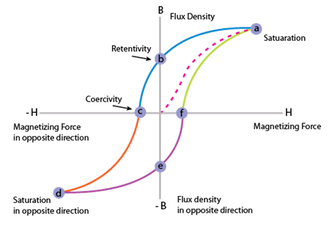
1. After applying the magnetic field, indications that form must interpreted. This process requires that the inspector distinguish between relevant and non-relevant indications.
2. The following series of images depict relevant indications produced from a variety of components inspected with the magnetic particle method.

A longitudinal magnetic field is usually established by placing the part near the inside or a coil’s annulus. This produces magnetic lines of force that are parallel to the long axis of the test part.
Field direction for flaw detection :
For maximum detection sensitivity the magnetic field should be 90 Degree to the major dimension of the flaw. However magnetic field direction up to 45 Degree to the major dimension may produce detectable indications.
The required magnetic field can be introduced into a component in a number of different ways.
1.Using a permanent magnet or an electromagnet that contacts the test piece
2.Flowing an electrical current through the specimen
3.Flowing an electrical current through a coil of wire around the part or through a central conductor running near the part.
